Research Article | | Peer-Reviewed

Numerical Investigation of the Performance of a Vortex Tube-Based Vehicle Cabin Cooling System

Received: 3 September 2026     Accepted: 14 September 2026     Published: 21 October 2026
Views:       Downloads:
Abstract

The vortex tube is a fundamental device that produces two different temperatures and low-pressure flows from a single compressed, high-pressure, high-temperature flow. It is a stationary device used to separate the compressed air into cold and hot streams. Its function is based on the concept of air vortex stream movement. Conventional automotive air conditioning systems use refrigerants and vapor compression cycles, which contribute to high energy use and greenhouse emissions. Therefore, this work focused on a numerical study of the performance of a vortex tube for vehicle cabin cooling system applications by considering the inlet nozzles, cold-end diameter, and hot-tube length. The study was conducted with various inlet pressures from 4 to 7 bar, cold mass fractions from 0.3 to 0.5, and hot-tube parameters using a tube length of 106mm as a baseline, and also length-to-diameter ratios of 10, 15, and 20. The results show that increasing inlet pressure increases cooling capacity but reduces the coefficient of performance, while a higher cold mass fraction improves cooling load with moderate efficiency gains. The hot-tube length optimization showed that longer tubes slightly increase cooling capacity, but do not significantly improve the coefficient of performance, which indicates diminishing returns beyond a length-to-diameter ratio of approximately 10 to 15. Similarly, the cold-end diameter optimizations indicated that a strong influence was observed with the best configuration of hot tube length 115mm per unit tube diameter 1.4mm and 8 mm cold-end diameter at 4bar inlet pressure and cold mass fraction of 0.5 achieved a cooling load of 119W at COP 0.232. Finally, this study concludes that hot tube length offers incremental gains, while cold-end geometry is the key driver for improving vortex tube performance in vehicle cooling systems.

Published in International Journal of Mechanical Engineering and Applications (Volume 14, Issue 5)
DOI 10.11648/j.ijmea.20261405.13
Page(s) 114-126
Creative Commons

This is an Open Access article, distributed under the terms of the Creative Commons Attribution 4.0 International License (http://creativecommons.org/licenses/by/4.0/), which permits unrestricted use, distribution and reproduction in any medium or format, provided the original work is properly cited.

Copyright

Copyright © The Author(s), 2026. Published by Science Publishing Group

Keywords

Cold Mass Fraction, Computational Fluid Dynamics, Length to Diameter Ratio, Non-Air-conditioning, Coefficient of Performance, Vapour Compression Cycles

1. Introduction
The vortex tube is a fundamental device for producing two different temperatures and low-pressure flows from a single compressed, high-pressure, high-temperature flow. The vortex tube is also known as the Hilsch vortex tube , Ranque vortex tube , Ranque-Hilsch vortex tube , and Maxwell-Demon vortex tube . A vortex tube is a stationary device that has no moving parts at all and can produce two streams of different temperatures from a single injection flow. The working principle of a vortex tube is to first inject the compressed gas tangentially at high velocity through the inlet, and then separate it into two different temperature streams and exhaust via the cold and hot outlets.
The flow nature of the vortex tube follows swirl streaming. The swirl-streaming flow is of major significance in common industrial applications such as turbomachinery devices, furnaces, combustors, mixing, dust collectors, separations, and others. The fluid flow in different cross sections has various static and dynamic pressures . The vortex tube alone generates hot and cold flow streams with different cross sections of hot and cold streaming portions. Despite the vortex tube's simple design, the energy separation processes are extremely complex. The vortex tube does not require any exertion or heat exchange with the surrounding environment. Consequently, the separation effect is due to an internal energy interaction between the two flows . The vortex tube, due to its design simplicity, quietness, compactness, and lightweight, is widely used in industrial heating and cooling applications . It is also widely used in other application areas like sustainable energy utilization , vehicle exhaust , energy separation , and refrigerators . In comparison to other commercial refrigeration devices, the vortex tube has the following advantages: simple, low cost, no moving parts, no electricity or chemicals, small and lightweight, maintenance-free, instant cold air, durable due to the clean working media and stainless steel, and temperature adjustable. However, its low thermal efficiency is a major limitation for its application .
The traditional vehicle air conditioning system relies heavily on refrigerants such as hydrofluorocarbons, which contribute significantly to global warming and environmental degradation. Vortex tube refrigeration for vehicle cabin cooling systems is an essential way to reduce dependency on traditional air conditioning. Many studies have shown that the vortex tube can be modified for automotive applications, especially in heavy trucks and low commercial vehicles, where compressed air is readily available . The growing demand for energy-efficient and environmentally friendly cooling solutions in the automotive industry has prompted researchers to investigate alternatives to traditional vapor-compression refrigeration systems. A vortex tube air conditioning system can reduce energy use and eliminate hazardous refrigerants, and its compact design makes it ideal for installation in tight car spaces. Although vortex tubes have been extensively studied for both industrial spot cooling and overall thermodynamic performance, there is still a shortage of research focusing on their integration into vehicle cabin systems. More studies are now available, many of which use standard geometries without improving nozzle design, tube length, or diameter ratios for automotive applications.
Furthermore, even though experimental results are available, this topic is being examined using thorough computational fluid dynamics models that capture turbulence, energy separation, and flow behavior inside vortex tubes. As a result, the goal of this research is to bridge the gaps by designing and optimizing vortex tube geometry using computational fluid dynamics simulations to improve cooling performance and achieve an energy-efficient alternative to conventional vehicle air conditioning systems, as well as to develop unique cooling systems that reduce environmental effects while maintaining passenger comfort.
2. Materials and Methods
2.1. Concept of Vortex Tube System Development
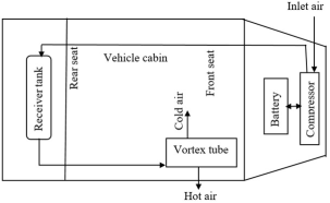
The vortex tube refrigeration system for automotive applications is designed to cool various components with compressed air, providing a compact, maintenance-free alternative to typical heating, ventilation, and air conditioning systems. It is integrated into a vehicle seat ventilation system. The vortex tube has key components like a compressed air source, a cold air delivery system, heat dissipation systems, and a control system. The compressed air is obtained with the vehicle's on-board air compressor. The cold air delivery and heat dissipation systems, on the other hand, serve as ducting routes for cold air to a vehicle cabin ventilation system and to the exterior of the cabin or heat recovery system, respectively. Similarly, sensor-based control systems monitor temperature and pressure parameters.
Figure 1 shows the installation of the vortex tube in the vehicle cabin, and the cold air outlet connects to the cabin ducting with insulated tubing. The duct material must be thermally insulated for cold air to prevent heat gain and corrosion-resistant materials for durability under high-pressure air. The hot-air outlet vents externally or onto a heat exchanger. Airflow control valves regulate the mix of vortex tube output with ambient or recirculated air.
Figure 1. Schematic diagram of the vortex tube in the vehicle cabin.
Therefore, the model and study of the vortex tube were conducted based on the above criteria.
2.2. Geometrical Modeling of the Vortex Tube
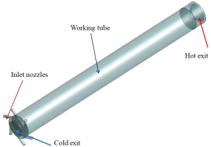
The vortex tube was modelled with ANSYS DesignModeler, as shown in Figure 2. In this model, the inlet includes six separate nozzles, and the hot outlet is considered for computation as a flat plate. The venturi tube consists of several critical parts, such as the inlet nozzle, vortex chamber, cold orifice, hot tube, and control valves. The inlet nozzle serves for the tangential entry of the compressed air. It has six nozzles. The vortex chamber, which is a cylindrical zone that spins the air rapidly. The cold orifice is a small outlet near the centre for cold air, and the hot tube is the long outlet tube for hot air. Similarly, the control valve regulates the flow split between the hot and cold streams.
Figure 2. Geometrical model of a vortex tube.
2.3. Governing Equations and Boundary Conditions
The computational fluid dynamics studies were conducted in a vortex tube, steady-state, and viscous incompressible fluid flow controlled by the Navier-Stokes equations, i.e., continuity, momentum, and energy equations. In addition, the absolute velocity formulation and the steady state were chosen. Equations 1, 2 to 4, and 5 are the continuity, momentum, and energy equations, respectively. Similarly, equation 6 is the state equation.
∇.ρv⃗+∂ρ∂t=0(1)
∂ρu∂t+∂ρu2∂x+∂ρuv∂y+∂ρuw∂z=-∂p∂x+∂∂xλ∇∙v+2μ∂u∂x+∂∂yμ∂v∂x+∂u∂y+∂∂zμ∂u∂z+∂w∂x+ρfx(2)
where ρ is the fluid density (kg/m3). u, v, and w are the velocity components in the x, y, and z directions, respectively. In addition, t is the time variable (s). fx is the body force per unit mass in the x-direction. μ is the dynamic viscosity. λ is the second viscosity coefficient. ∇.v=∂u∂x+∂v∂y+∂w∂z is the divergence of the velocity vector field. ∂∂x, ∂∂y, and ∂∂z are the derivatives with respect to spatial coordinates. ∂u∂t is the local change of momentum in the x-direction. ∂p∂x is the pressure gradient force in the x-direction. ∂ρu2∂x,  ∂ρuv∂y, and ∂ρuw∂z are the convective transport of momentum in the x-direction.
∂ρv∂t+∂ρuv∂x+∂ρv2∂y+∂ρvw∂z=-∂p∂y+∂∂xμ∂v∂x+∂u∂y+∂∂yλ∇∙v+2μ∂v∂y+∂∂zμ∂w∂y+∂v∂z+ρfy(3)
where ∂ρv∂t is the local change of y-momentum. ∂ρuv∂x, ∂ρv2∂y, and ∂ρvw∂z are the convective transport of y-momentum due to fluid motion in the x, y, z directions. -∂p∂y is the pressure gradient force in the y-direction. ∂∂xμ∂v∂x+∂u∂y is the viscous shear stress contribution from x-gradients. ∂∂yλ∇∙v+2μ∂v∂y is the normal viscous stress in the y-direction. ∂∂zμ∂w∂y+∂v∂z is the normal shear stress contribution from the z-gradient. ρfy is the body force per unit mass in the y-direction.
∂ρw∂t+∂ρuw∂x+∂ρvw∂y+∂ρw2∂z=-∂p∂z+∂∂xμ∂u∂z+∂w∂x+∂∂yμ∂w∂y+∂v∂z+∂∂zλ∇∙v+2μ∂w∂z+ρfz(4)
where ∂ρw∂t is the local change of z-momentum. ∂ρuw∂x, ∂ρvw∂y, and ∂ρw2∂z are the convective transport of z-momentum due to fluid motion in the x, y, and z directions. ∂p∂z is the pressure gradient force in the z-direction. ∂∂xμ∂u∂z+∂w∂x is the viscous shear stress contribution from x-gradients. ∂∂zμ∂w∂y+∂v∂z is the normal viscous stress 5in the y-direction. ∂∂yλ∇∙v+2μ∂w∂z is the normal shear stress contribution from the z-gradient. ρfz is the body force per unit mass in the y-direction.
ρDDte+V22=ρq+∂∂xk∂T∂x+∂∂yk∂T∂y+∂∂zk∂T∂z-∂up∂x-∂vp∂y-∂wp∂z+∂uτxx∂x+∂uτyx∂y+∂uτzx∂z+∂vτxy∂x+∂vτyy∂y+∂vτzy∂z+∂wτxz∂x+∂wτyz∂y+∂wτzz∂z+ρf∙V(5)
where ρ is fluid density (mass/m3), DDt=∂∂t+u∂∂x+v∂∂y+w∂∂z is the material derivative, and e is the internal energy per unit mass. v22 is the kinetic energy per unit mass. v2=u2+v2+w2, q is the volumetric heat source. K is the thermal conductivity. T is the temperature field. P is the pressure field. u, v, and w are velocity components in the x, y, and z directions. τxx, τyy, and τzz are the normal stresses. τxy, τyx, τxz, τzx, τyz, and τzy are shear stresses. ρf∙V is the work done by body forces.
P=ρRT(6)
where ρ is the fluid density (Kg/m3), P is the pressure (Pa), T is the temperature (K), R is the ideal gas constant (J/mol. K). A pressure-based solver was selected. The pressure is determined by solving the mass continuity and momentum equations. Additionally, absolute velocity and steady-state formulations were selected. The Reynolds number is defined as the ratio of inertial forces (which push the fluid forward) to viscous forces, which resist motion. This means Re=ρ×v×lμ, where ρ is the density of air, v is the velocity of inlet air, l is the characteristic length of the inlet nozzle, and μ is the dynamic viscosity of air.
The k- ε turbulence model, based on the eddy viscosity hypothesis was used to represent a viscous incompressible flow with turbulence intensity. Therefore, the turbulence kinetic energy, k, and its rate of dissipation, ε are obtained from the following transport equations
∂∂tρk+∂∂xiρkui=∂∂xj∂k∂xjμ+μtσk+Gk+Gb-ρε-YM+Sk(7)
∂∂tρε+∂∂xiρϵui=∂∂xj∂ε∂xjμ+μtσε+C1ϵϵkGK+C3ϵGb-C2ϵρϵ2k+Sε(8)
In the above equations, GK represents the generation of turbulent kinetic energy due to the mean velocity gradients. Gb is the generation of turbulent kinetic energy due to buoyancy. YM is the contribution of fluctuating dilation in compressible turbulence to the overall dissipation rate. C1ϵ, C2ϵ, and C3ϵ are constants. σε and σk are the Prandtl numbers for ε and ĸ, respectively. Sε and Sε are user-defined source terms. The turbulent or eddy viscosity (μt) is computed by combining ε and ĸ as follows .
μt=ρCμk2ϵ(9)
The modelled geometry is based on the Exair 708 SLMP vortex tube model as shown in Table 1. It is an axisymmetric model of the tube matching geometrical properties to the vortex tube used by .
Table 1. Geometrical parameters of the vortex tube.

Component name

Parameters

Value (mm)

Inlet Nozzle

Nozzle height

0.97

Nozzle width

1.41

Cold exit

Cold exit diameter

6.2

Hot exit

Hot exit diameter

11

Working tube

Working tube length

106

Working tube internal diameter

11.4

Table 2 shows the boundary conditions and variables for the vortex tube study.
Table 2. Boundary conditions.

Boundaries

Type

Variables

Values

Inlet

Stagnation inlet

Pressure

4.83bar

Temperature

294.2k

Turbulence intensity

5%

Cold outlet

Pressure outlet

Pressure

1bar

Temperature

294.2k

Hot outlet

Pressure and temperature outlet

Pressure

1.4, 1.5, 1.6, 1.7 bar)

Temperature

294.2K

Wall

Shear stress and thermal specification

Shear stress specification

Stationary and no-slip

Thermal specification

Adiabatic

2.4. Mesh Independence Test
The process of meshing is extremely critical, and great care needs to be taken to create a mesh in order to capture the correct fluid flow behaviour. The mesh independence test is performed during computation to determine the optimal mesh grid quality. Its main objectives to minimize the computational time and maintain the accuracy of the results. Mesh independence study in vortex tube simulations is most critical for the wall surfaces of the inner tube wall, nozzle, cold and hot exits, because these are where boundary layers, shear stresses, and heat transfer strongly influence the accuracy of the results.
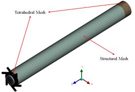
Figure 3 illustrates the discretization of a vortex tube. The structured mesh is done by sweeping a source face through a body to a target face. The sweep mesh involves generating a mesh on one face, or the source face, and then “sweeping” that mesh through the volume to the opposite face, or the target face. This results in a structured mesh typically composed of hexahedral elements, which are preferred for their accuracy and efficiency in simulations. It is ideal for bodies with two topologically identical faces, like revolved shapes, cylinders, and extrusions. The sweep method is beneficial for achieving consistent mesh distribution along the sweep direction. Tetrahedral components are also used around the nozzle and vortex chamber. Tetrahedral meshes are excellent at representing geometry and turbulent flows. It separates the 3D domain into small tetrahedral units, allowing for precise resolution of curved surfaces and internal vortices. It supports adaptive refinement, meaning areas with high gradients are meshed densely, such as the vortex core meshed densely. It optimizes the tube geometry for maximum cooling performance.
Figure 3. Vortex tube geometrical mesh at 5.5mm.
All meshes show that there is no significant difference in vortex tube performance output, such as COP. This means the performance of the vortex tube is almost similar to small errors or insignificance in each element's size. The maximum and minimum element sizes are 545680 and 93388 at 0.5mm and 5.5mm element sizes, respectively. Table 3 demonstrates how multiple discretization meshes are used to save computational time and provide accurate results. The mesh grid includes element sizes ranging from 0.5 to 5.5mm.
Table 3. Grid independence study.

Element size (mm)

No. elements

Tcold (k)

ΔTcold (k)

Thot (k)

ΔThot (k)

ΔPcold (bar)

ΔPhot (bar)

Qcold (w)

W (w)

COP

5.5

93388

268.88

25.32

307.88

13.68

4.95

4.17

109.42

683.71

0.160

4.5

94478

268.99

25.21

307.93

13.73

4.95

4.18

108.94

683.71

0.159

3.5

96177

268.90

25.30

308.05

13.85

4.96

4.18

109.33

683.71

0.159

2.5

98418

268.84

25.36

308.09

13.89

4.95

4.18

109.59

683.71

0.160

1.5

115432

267.95

26.25

307.82

13.62

4.94

4.17

110.80

683.71

0.162

0.5

545680

266.50

27.70

309.92

15.72

4.79

4.30

122.48

719.69

0.170

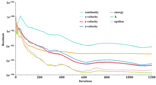
Figure 4. Convergence test at 98418 elements.
All meshes indicate no significant difference in pressure change or coefficient of discharge. The maximum number of elements is 545680, with a small element size of 0.5 mm. Similarly, the number of elements decreases as the element size increases to 5.5mm. However, in all circumstances, the difference between COP and other output metrics is minor. As a result, an element size of 2.5mm was used for all case simulations to maximize computing efficiency. On the other side, the convergence of residues shows high quality. Figure 4 depicts the convergence of a 2.5mm grid element size up to 1000 iterations. After 1000 iterations, the iterative convergences of all residues were less than 10-3.
3. Result and Discussion
3.1. Flow Visualization
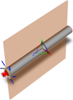
The computational output parameters are evaluated based on the following positions of the cutting plane, as shown in Figure 5. The study focused on simulating the flow and evaluating the performance of COP. Therefore, the numerical evaluation is visualized by aligning the cutting plane along the z-axis.
Figure 5. The position of a cutting plane to show the computational output parameters.
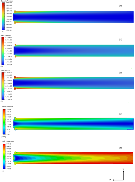
Figure 6 shows the flow contour visualization of the pressure, velocity, and temperature magnitudes along the vortex tube. The contour flow visualization of pressure, velocity magnitude, and temperature along the flow vortex tube has a length of 106 mm and a pressure inlet (Pin) of 4.83 bar.
Figure 6 (a), (b), and (c) demonstrate the dynamic, static, and total pressures, respectively. The total pressure is very high at the nozzle inlets. Figure 6 (d) shows the velocity magnitudes along the cutter plane of the vortex tube. Similarly, Figure 6 (e) shows the temperature streamlines of the vortex tube on the cutter surface.
Figure 6. Contour flow visualization: (a) Dynamic pressure, (b) Static pressure, (c) Total pressure, (d) Velocity magnitude, and (e) Temperature streamline.
3.2. Effect of Hot Tube Length, Inlet Pressure, and Cold Mass Fraction on Cooling Performance of Vortex Tube
The numerical studies were conducted to evaluate the influence of tube length using 106 mm, 115 mm, 170 mm, and 210 mm under varying inlet pressures (Pin) from 4 to 7 bar and cold mass fractions (CMF) from 0.3 to 0.5. The results were analysed in terms of key performance indicators. The results are presented to systematically analyse the effect of these three parameters on vortex tube cooling performance. The analyzed results focused on basic parameters: cold outlet temperature (Tcold), coefficient of performance (COP), cooling capacity (Qcold), and temperature drop (∆Tcold) under varying hot tube lengths, CMF, and inlet pressure values. The analysis identifies optimal operating conditions that balance cooling power and efficiency, providing valuable insights for vortex tubes in vehicle cooling systems.
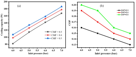
Figure 7 shows the effect of inlet pressure on the cooling loads and coefficient of performance (COP) of the vortex tube with different cold mass fractions (CMF). The inlet pressure affects the cooling capacity and the vortex tube performance.
Figure 7. Effect of inlet pressure with tube length 106mm at different CMF; (a) cooling capacity vs inlet pressure, (b) COP vs inlet pressure.
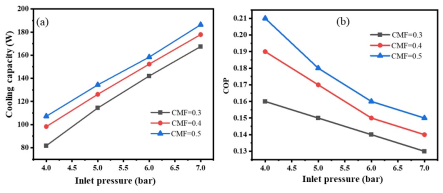
On the other hand, when the tube length is changed to 115mm, the cooling load and COP have a similar pattern. Figure 8 shows the impact of inlet pressure on the cooling capacity for the second tube length of 115mm for different cold mass fractions and compressed air inlet pressures. Figure 8 (a) illustrates the trade-off between cooling capacity Qcold and Figure 8 (b) efficiency in terms of COP with similar inlet pressure Pin increases under different CMF values. In all conditions, the cooling capacity rises steadily with inlet pressures; this means the system can deliver more cooling power at higher pressures. However, COP consistently declines, indicating that the performance efficiency drops and more input work is required to achieve the added cooling. At Lower inlet pressure values, higher CMF values of 0.4 and 0.5 provide both greater cooling and better efficiency compared to CMF 0.3, but as Pin increases, the efficiency decreases.
In general, the results highlight that while increasing Pin enhances cooling capacity, it arises at the cost of reduced efficiency, and the choice of CMF effects the balance between these two performance measures.
Figure 8. Effect of inlet pressure with tube length 115 mm at different CMF; (a) Cooling capacity vs inlet pressure, (b) COP vs inlet pressure.
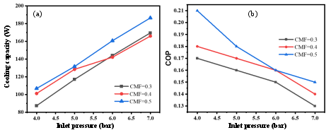
Similarly, the investigation was conducted on the tube length of 170 mm. Figure 9 shows that for length of hot tube at 170mm and different cold mass fractions and compressed air inlet pressures. The results show that as the inlet pressure (Pin) increases from 4 to 7 bar, the cooling capacity (Qcold) consistently rises across all cold mass fractions (CMFs), indicating that higher pressure enhances the vortex tube’s ability to deliver cooling power. However, the coefficient of performance (COP) shows the opposite trend, steadily decreasing with Pin, which indicates that efficiency drops, as more work input is required to achieve the added cooling. At lower Pin values, higher CMF values of 0.4 and 0.5 provide both stronger cooling and better efficiency compared to CMF 0.3, but at higher Pin the efficiency advantage narrows even though Qcold remains highest for CMF 0.5. Overall, the graphs highlight a clear trade off: increasing Pin improves cooling capacity for vehicle cabin applications, but careful optimization of CMF and vortex tube length is needed to preserve efficiency and balance energy consumption.
Figure 9. Effect of inlet pressure with tube length 170mm at different CMF; (a) Cooling capacity vs inlet pressure, (b) COP vs inlet pressure.
Finally, the study was also conducted at a hot tube length of 210 mm for different variables, as shown in Table 4. The result shows that the performance of the tube depends on inlet pressure, mass fraction, and inlet temperature. The result shows that cooling capacity (Qcold) and coefficient of performance (COP) with different inlet pressures (Pin) and cold mass fractions (CMF) reveal a distinct performance trade-off inherent to vortex tube operation. As Pin increases from 4 to 7 bar, Qcold exhibits a consistent upward trend for all CMF values, indicating that higher inlet pressure enhances the cooling potential of the system. However, this improvement in cooling capacity is accompanied by a steady decline in COP, signifying reduced thermodynamic efficiency due to the increased work input required at elevated pressures. Among the CMF values tested, at CMF 0.5 consistently delivers the highest cooling capacity, while also achieving superior COP at lower Pin values, particularly at 4 bar where COP reaches 0.21. Conversely, at higher Pin values, the efficiency advantage of increased CMF diminishes, even though Qcold remains highest. These results underscore the necessity of balancing cooling output and energy efficiency in vortex tube applications, particularly for vehicle cabin cooling systems where both performance and energy consumption are critical. The findings suggest that optimal operation may be achieved at moderate Pin values of 5 and 6 bar with CMF in the range of 0.4 and 0.5, thereby maximizing the cooling performance while mitigating efficiency losses.
Table 4. COP with hot tube length 210mm and different parameters.

Pin (bar)

CMF

Tcold (k)

Thot (k)

ΔTcold (k)

ΔThot (k)

Qcold (w)

W(w)

COP

4

0.3

263.23

305.41

31

11.21

87.23

512.94

0.17

0.4

267.86

309.13

26.34

14.93

100.59

512.94

0.19

0.5

272.16

313.12

22.04

18.92

106.32

512.94

0.20

5

0.3

263.68

307.54

30.52

13.48

116.56

739.65

0.16

0.4

266.57

310.53

27.63

16.33

127.73

739.65

0.17

0.5

269.64

313.86

24.56

19.66

133.28

739.65

0.18

6

0.3

263.80

309.07

30.4

14.87

143.59

987.04

0.14

0.4

265.89

311.48

28.31

17.28

153.64

987.04

0.15

0.5

268.09

314.23

26.11

20.03

160.06

987.04

0.16

7

0.3

264.31

310.99

29.89

16.79

153.20

1177.87

0.13

0.4

265.92

313.14

28.28

18.94

173.37

1177.87

0.14

0.5

267.92

315.76

26.28

21.56

179.60

1177.87

0.15

In general, the results indicated that the shorter lengths of 106mm and 115mm achieve higher COP values up to 0.21 at tube length of 115 mm, Pin at 4 bar, and CMF 0.5. Provide a larger temperature drop (ΔTcold) at the cold end, especially at a lower CMF value of 0.3. Cold power output (Qcold) is moderate compared to longer tubes. On the other hand, for the longer lengths of 170 mm and 210 mm, COP values remain similar with a maximum value of 0.21, but cold power (Qcold) increases significantly with pressure and CMF. The temperature drop ∆Tcold decreases slightly compared to shorter tubes, indicating less cooling intensity but more balanced energy distribution. Increasing the Pin from 4 to 7 bar, the Qcold rises sharply from 80W at 4 bar to 180W at 7 bar. In addition, the COP decreases with higher Pin dropping from 0.21 to 0.13. This shows that a trade-off between higher pressures improve the cooling capacity but reduce efficiency. The effect of cold mass fraction (CMF) at 0.3 maximum temperature drop ΔTcold of 31K is observed; this means a stronger cooling effect. However, COP is lower from 0.13 to 0.16. At a higher CMF value of 0.5, ΔTcold reduces, but COP improves from 0.18 to 0.21. This indicates that higher CMF favours efficiency over cooling intensity. Optimal conditions and the best COP value of 0.21 occur at tube length 115 to 170mm, Pin 4 bar, and CMF 0.5. Similarly, the best cooling effect temperature drop ΔTcold 31k occurs at lengths 106mm to 210mm, Pin 4bar, and CMF 0.3. Similarly, the best cold power output Qcold186W occurs at length 115mm to 170mm, Pin 7 bar, and CMF 0.5.
Therefore, for vehicle cabin cooling, a vortex tube length of 115 mm at Pin 4bar, CMF 0.5 is the most practical choice: It balances COP or efficiency with adequate cooling power. It avoids excessive compressed air consumption. It provides sufficient ΔTcold to maintain cabin comfort in passenger cars. The longer tubes from 170mm to 210mm can be employed in heavy-duty vehicles that demand higher cooling loads.
3.3. Effect of Cold End Diameter and Inlet Nozzle Diameter on the Cooling Capacity of Vortex Tube
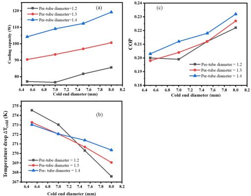
The numerical study is conducted to study the effect of cold end diameter and inlet nozzle diameter on a vortex tube of length 115 mm, operating at an inlet pressure Pin of 4 bar, and a cold mass fraction of 0.5. It combines variations in single-jet inlet nozzle diameter from 1.2 to 1.4 mm with cold end diameters from 6.5 to 8 mm to evaluate their combined effect on Qcold, ΔTcold, and COP. The main purpose is to identify the optimal configuration that maximizes Qcold while maintaining acceptable temperature separation and efficiency.
Figure 10 shows that increasing the cold end diameter from 6.5mm to 8mm consistently decreases the cold outlet temperature Tcold and increases the temperature drop ΔTcold. At a per-tube diameter of 1.2 mm, Tcold is decreased from 274.54K at 6.5mm to 267.59K at 8mm, with ΔTcold rising from 19.66K to 26.61K. This trend indicates that larger cold end diameters enhance cooling effectiveness. As the tube diameter (or single tube diameter) increased from 1.2mm to 1.4mm, the cooling capacity (Qcold) improved significantly. At a 6.5mm cold end diameter, Qcold rose from 77.06W at 1.2 mm to 104.25W at 1.4 mm. However, this came with higher input work of 384.7W at 1.2mm and 512.94W at 1.4mm. The COP values improved with larger cold end diameters, reaching a maximum of 0.232 per tube diameter of 1.4 mm and cold end diameter of 8 mm.
Figure 10. Effect of cold end diameter and inlet nozzle diameter on vortex tube cooling performance; (a) Cooling capacity vs cold end diameter, (b) COP vs cold end diameter at different inlet nozzle diameters, (c) Temperature drop vs cold end diameter at different inlet nozzle diameters.

Therefore, for a vehicle cabin cooling application, the 1.4mm per tube diameter with 8 mm cold end diameter offers the best compromise between cooling capacity, efficiency, and manageable input work.
3.4. Discussions
The vortex tube's basic parts are the diaphragm, nozzle, cylindrical tube, chamber, cone valve, cold and hot air outlets; a diffuser is sometimes inserted between the hot valve and the cylindrical tube outlet. The fundamental working principle is based on the pressure difference, which causes the airstream to separate. When compressed air is injected tangentially into the chamber through the nozzle, swirls form due to the difference in pressure that causes the compressed air to separate into two air streams i.e. cold and hot air streams. The numerical investigation provided valuable insight into the flow and thermal separation inside the vortex tube. However, it is necessary to verify the computational results with experimental results to confirm and evaluate the results. The result validation ensures that the numerical model represents the real physical behaviour seen in reality to reproduce theoretical expectations. Therefore, the results obtained for vortex tube performance are systematically compared with published experimental findings with the key performance indicators, such as cold end temperature, cooling capacity, temperature drop, and coefficient of performance (COP). The results shows that strongly agree with the research done by Celik et al. 2020 on the vortex tube, which focused on utilizing the hot stream of the vortex tube to assist diesel engine cold starts, and the thermodynamic separation mechanism is identical to the current model. In both studies, the vortex tube produces two streams with significant temperature differences of cold and hot streams. The experimental paper reported that the temperature differences of approximately 20 to 30K and COP values in the range of 0.15 to 0.25. Whereas the current study focused on the cold stream for cabin cooling, predict ΔTcold from 20 to 27K and COP from 0.20 to 0.23 under comparable operating conditions. These values fall squarely within the experimentally observed ranges, confirming that the numerical model accurately represents the vortex tube’s energy separation process. On the other hand, the current results on tube lengths of 106 to 210mm and cold end diameter optimization at 115mm show COP values in the range of 0.13 to 0.23, cooling loads up to 186W, and ΔTcold between 22 to 31K. These values are consistent with the study by Kim et al. 2020 , which focused on a vehicle air conditioning system using a vortex tube and reported COP from 0.2 to 0.25 and similar cooling trends under automotive-relevant pressures.
The study highlighted that the tube length beyond 115mm adds little benefit, while cold end diameter tuning significantly affects COP and Qcold. The ΔTcold values from 22 to 27K aligned tightly with other scholarly works in the 20 to 30K range. In addition, the cooling loads of 100 to 180W fall directly within other experimental works, and it strengthening the current study results. The optimal design point is a length of 115 mm, Pin from 5 to 6 bar, CMF 0.5, and cold end diameter from 7.5 to 8 mm. This confirms that the current model result is reliable for design optimization and matches the feasibility ranges reported in other scholarly works.
The Tcold is 268 to 272 K under 4 to 6 bar, with a COP from 0.20 to 0.23, peaking with favourable geometry and CMF; Qcold increases with Pin, and COP flattens or dips due to rising compressor work. The shorter hot tube 115 mm maintains separation with better compactness; a larger cold-end diameter 8 mm boosts Qcold and COP for practical comfort without sacrificing energy separation. A compact module at tube length 115 mm, scaled in parallel, can meet 300 to 600W with 3 to 6 tubes for cabin-cooling targets with controllable supply air and dehumidification. With acceptance criteria set to temperature ±1 K, capacity ± 8%, and COP ≥ 0.21, a simple bench program will complete the experimental confirmation while leaving the published report intact.
The current optimized vortex tube design can be used as an auxiliary cabin cooling option for automobiles without air conditioning. The integration strategy of a vortex tube refrigeration system refers to the process of combining the vortex tube into a larger system for cooling. It is about connecting, controlling, and optimizing vortex tube temperature regulation within an automotive engine or cabin cooling system. The strategy involves combining the vortex tube with existing vehicle systems to improve cooling efficiency. Based on the current results, the researchers recommend that interested researchers continue to consider adaptive control of cold mass fraction and inlet pressure to tailor cooling performance to transient cabin demands, ensuring energy efficiency while maintaining comfort. Finally, the authors conclude that the vortex tube can be an alternative and supplement to the vehicle cabin cooling system.
4. Conclusion
The vortex tube is a stationary device that has no moving parts at all. In other words, a thermal device produces two streams of different temperatures from a single injection flow. The numerical analysis of the vortex tube for a vehicle cabin cooling system demonstrates that while cooling capacity increases with higher inlet pressure and cold mass fraction, the coefficient of performance tends to decline due to the rising compressor power requirement.
Among the studied configurations, the optimized cold-end diameter of 8 mm combined with a per-tube diameter of 1.4 mm at 4 bar and CMF of 0.5 achieved the best balance, delivering a cooling load of about 119 W with a COP of 0.232. These findings indicate the vortex tube's promise for localized or supplemental cooling applications, but they also emphasize the limits in achieving entire cabin cooling when compared to traditional vapour-compression systems. The findings are consistent with previous research that emphasizes vortex tubes' effectiveness in transient thermal management tasks such as diesel engine cold-start and catalyst light off, but they also highlight the challenge of low COP and high compressed-air demand when used for continuous cabin cooling. Finally, adaptive control of cold mass fraction and inlet pressure should be implemented to tailor cooling performance to transient cabin demands, ensuring energy efficiency while maintaining comfort.
Abbreviations

CMF

Cold Mass fraction

COP

Coefficient of Performance

Qcold

Cooling Power

Qheat

Heating Power

Tcold

Cold Temperature

ΔTcold

Cold Temperature Difference

ΔThot

Hot Temperature Difference

Thot

Hot Temperature

W

Power

Pin

Inlet Pressure

A

Cross-Sectional Area

Author Contributions
Sintayehu Assefa Endaylalu: Conceptualization, Formal Analysis, Methodology, Supervision, Writing – original draft, Writing – review & editing
Genet Tesfaye Degene: Conceptualization, Formal Analysis, Methodology, Writing – original draft, Writing – review & editing
Data Availability Statement
The data that support the findings of this study are available from the corresponding author upon reasonable request.
Conflicts of Interest
The authors declare no conflict of interest.
References
[1] Hilsch, R., The use of the expansion of gases in a centrifugal field as cooling process. Review of Scientific Instruments, 1947. 18(2): p. 108-113.
[2] Ranque, G., Experiments on expansion in a vortex with simultaneous exhaust of hot air and cold air. J. Phys. Radium, 1933. 4(7): p. 112-114.
[3] Gao, C., et al., Experimental study on a simple Ranque-Hilsch vortex tube. Cryogenics, 2005. 45(3): p. 173-183.
[4] Rahman, S. and A. Mujumdar, Aerodynamic and thermal characteristics of a maxwell type vortex tube. Open Engineering, 2011. 1(4): p. 369-379.
[5] Endaylalu, S. A., A Numerical and Experimental Investigation of Fluid Flow Through a Venturi Tube. American Journal of Mechanical and Industrial Engineering, 2025. 10: p. 116-127.
[6] Hamdan, M. O., S.-A. Al-Omari, and A. S. Oweimer, Experimental study of vortex tube energy separation under different tube design. Experimental Thermal and Fluid Science, 2018. 91: p. 306-311.
[7] Wang, C., et al., Cooling and anti-friction effects of vortex tube cryogenic minimum quantity lubrication in milling of 3D printed iron-nickel alloy. Journal of Cleaner Production, 2024. 434: p. 139900.
[8] Vashisth, S., V. Kumar, and K. D. Nigam, A review on the potential applications of curved geometries in process industry. Industrial & Engineering Chemistry Research, 2008. 47(10): p. 3291-3337.
[9] Belov, G., et al. The Vortex Aircooler System for Cutting Materials in Aerospace Industry. in MATEC Web of Conferences. 2018. EDP Sciences.
[10] Gutak, A. D., Experimental investigation and industrial application of Ranque-Hilsch vortex tube. International Journal of Refrigeration, 2015. 49: p. 93-98.
[11] Rostami, A. B. and M. Armandei, Renewable energy harvesting by vortex-induced motions: Review and benchmarking of technologies. Renewable and Sustainable Energy Reviews, 2017. 70: p. 193-214.
[12] Zhang, B. and X. Guo, Prospective applications of Ranque-Hilsch vortex tubes to sustainable energy utilization and energy efficiency improvement with energy and mass separation. Renewable and Sustainable Energy Reviews, 2018. 89: p. 135-150.
[13] Talawo, R.-C., B. E. Mtopi Fotso, and M. Fogue, Numerical study of a solar thermoelectric generator with vortex tube for hybrid vehicle. Numerical Heat Transfer, Part A: Applications, 2021. 80(1-2): p. 43-61.
[14] Kim, Y., S. Im, and J. Han, A Study on the Application Possibility of the Vehicle Air Conditioning System Using Vortex Tube. Energies, 2020. 13(19): p. 5227.
[15] Fotso, B. M., et al., Modeling and thermal analysis of a solar thermoelectric generator with vortex tube for hybrid vehicle. Case Studies in Thermal Engineering, 2019. 15: p. 100515.
[16] Talawo, R.-C., B. E. M. Fotso, and M. Fogue, An experimental study of a solar thermoelectric generator with vortex tube for hybrid vehicle. International Journal of Thermofluids, 2021. 10: p. 100079.
[17] Liang, F., et al., Experimental investigation on improving the energy separation efficiency of vortex tube by optimizing the structure of vortex generator. Applied Thermal Engineering, 2021. 195: p. 117222.
[18] Tang, G., et al., Influence of flow straightener structure on energy separation performance of Ranque-Hilsch vortex tube based on energy and exergy analyses. Applied Thermal Engineering, 2023. 233: p. 121062.
[19] Promvonge, P. and S. Eiamsa-ard, Investigation on the vortex thermal separation in a vortex tube refrigerator. Science Asia, 2005. 31(3): p. 215-223.
[20] Valipour, M. S. and N. Niazi, Experimental modeling of a curved Ranque-Hilsch vortex tube refrigerator. International journal of refrigeration, 2011. 34(4): p. 1109-1116.
[21] Bovand, M., et al., Application of Response Surface Methodology to optimization of a standard Ranque-Hilsch vortex tube refrigerator. Applied Thermal Engineering, 2014. 67(1-2): p. 545-553.
[22] P. M. Khanwalkar, A. A.a., A Review on Enhancement of Refrigeration Effect of Vortex Tube. International Journal of Current Engineering and Technology (Special Issue-4): p. 213-218.
[23] Khalid, M. W. and M. Ahsan, Computational fluid dynamics analysis of compressible flow through a converging-diverging nozzle using the k-ε turbulence model. Engineering, Technology & Applied Science Research, 2020. 10(1): p. 5180-5185.
[24] Skye, H., G. Nellis, and S. Klein, Comparison of CFD analysis to empirical data in a commercial vortex tube. International journal of refrigeration, 2006. 29(1): p. 71-80.
[25] Celik, A., M. Yilmaz, and O. F. Yildiz, Improvement of diesel engine startability under low temperatures by vortex tubes. Energy Reports, 2020. 6: p. 17-27.
Cite This Article
  • APA Style

    Endaylalu, S. A., Degene, G. T. (2026). Numerical Investigation of the Performance of a Vortex Tube-Based Vehicle Cabin Cooling System. International Journal of Mechanical Engineering and Applications, 14(5), 114-126. https://doi.org/10.11648/j.ijmea.20261405.13

    Copy | Download

    ACS Style

    Endaylalu, S. A.; Degene, G. T. Numerical Investigation of the Performance of a Vortex Tube-Based Vehicle Cabin Cooling System. Int. J. Mech. Eng. Appl. 2026, 14(5), 114-126. doi: 10.11648/j.ijmea.20261405.13

    Copy | Download

    AMA Style

    Endaylalu SA, Degene GT. Numerical Investigation of the Performance of a Vortex Tube-Based Vehicle Cabin Cooling System. Int J Mech Eng Appl. 2026;14(5):114-126. doi: 10.11648/j.ijmea.20261405.13

    Copy | Download

  • @article{10.11648/j.ijmea.20261405.13,
      author = {Sintayehu Assefa Endaylalu and Genet Tesfaye Degene},
      title = {Numerical Investigation of the Performance of a Vortex Tube-Based Vehicle Cabin Cooling System},
      journal = {International Journal of Mechanical Engineering and Applications},
      volume = {14},
      number = {5},
      pages = {114-126},
      doi = {10.11648/j.ijmea.20261405.13},
      url = {https://doi.org/10.11648/j.ijmea.20261405.13},
      eprint = {https://article.sciencepublishinggroup.com/pdf/10.11648.j.ijmea.20261405.13},
      abstract = {The vortex tube is a fundamental device that produces two different temperatures and low-pressure flows from a single compressed, high-pressure, high-temperature flow. It is a stationary device used to separate the compressed air into cold and hot streams. Its function is based on the concept of air vortex stream movement. Conventional automotive air conditioning systems use refrigerants and vapor compression cycles, which contribute to high energy use and greenhouse emissions. Therefore, this work focused on a numerical study of the performance of a vortex tube for vehicle cabin cooling system applications by considering the inlet nozzles, cold-end diameter, and hot-tube length. The study was conducted with various inlet pressures from 4 to 7 bar, cold mass fractions from 0.3 to 0.5, and hot-tube parameters using a tube length of 106mm as a baseline, and also length-to-diameter ratios of 10, 15, and 20. The results show that increasing inlet pressure increases cooling capacity but reduces the coefficient of performance, while a higher cold mass fraction improves cooling load with moderate efficiency gains. The hot-tube length optimization showed that longer tubes slightly increase cooling capacity, but do not significantly improve the coefficient of performance, which indicates diminishing returns beyond a length-to-diameter ratio of approximately 10 to 15. Similarly, the cold-end diameter optimizations indicated that a strong influence was observed with the best configuration of hot tube length 115mm per unit tube diameter 1.4mm and 8 mm cold-end diameter at 4bar inlet pressure and cold mass fraction of 0.5 achieved a cooling load of 119W at COP 0.232. Finally, this study concludes that hot tube length offers incremental gains, while cold-end geometry is the key driver for improving vortex tube performance in vehicle cooling systems.},
     year = {2026}
    }
    

    Copy | Download

  • TY  - JOUR
    T1  - Numerical Investigation of the Performance of a Vortex Tube-Based Vehicle Cabin Cooling System
    AU  - Sintayehu Assefa Endaylalu
    AU  - Genet Tesfaye Degene
    Y1  - 2026/10/21
    PY  - 2026
    N1  - https://doi.org/10.11648/j.ijmea.20261405.13
    DO  - 10.11648/j.ijmea.20261405.13
    T2  - International Journal of Mechanical Engineering and Applications
    JF  - International Journal of Mechanical Engineering and Applications
    JO  - International Journal of Mechanical Engineering and Applications
    SP  - 114
    EP  - 126
    PB  - Science Publishing Group
    SN  - 2330-0248
    UR  - https://doi.org/10.11648/j.ijmea.20261405.13
    AB  - The vortex tube is a fundamental device that produces two different temperatures and low-pressure flows from a single compressed, high-pressure, high-temperature flow. It is a stationary device used to separate the compressed air into cold and hot streams. Its function is based on the concept of air vortex stream movement. Conventional automotive air conditioning systems use refrigerants and vapor compression cycles, which contribute to high energy use and greenhouse emissions. Therefore, this work focused on a numerical study of the performance of a vortex tube for vehicle cabin cooling system applications by considering the inlet nozzles, cold-end diameter, and hot-tube length. The study was conducted with various inlet pressures from 4 to 7 bar, cold mass fractions from 0.3 to 0.5, and hot-tube parameters using a tube length of 106mm as a baseline, and also length-to-diameter ratios of 10, 15, and 20. The results show that increasing inlet pressure increases cooling capacity but reduces the coefficient of performance, while a higher cold mass fraction improves cooling load with moderate efficiency gains. The hot-tube length optimization showed that longer tubes slightly increase cooling capacity, but do not significantly improve the coefficient of performance, which indicates diminishing returns beyond a length-to-diameter ratio of approximately 10 to 15. Similarly, the cold-end diameter optimizations indicated that a strong influence was observed with the best configuration of hot tube length 115mm per unit tube diameter 1.4mm and 8 mm cold-end diameter at 4bar inlet pressure and cold mass fraction of 0.5 achieved a cooling load of 119W at COP 0.232. Finally, this study concludes that hot tube length offers incremental gains, while cold-end geometry is the key driver for improving vortex tube performance in vehicle cooling systems.
    VL  - 14
    IS  - 5
    ER  - 

    Copy | Download

Author Information
  • Abstract
  • Keywords
  • Document Sections

    1. 1. Introduction
    2. 2. Materials and Methods
    3. 3. Result and Discussion
    4. 4. Conclusion
    Show Full Outline
  • Abbreviations
  • Author Contributions
  • Data Availability Statement
  • Conflicts of Interest
  • References
  • Cite This Article
  • Author Information